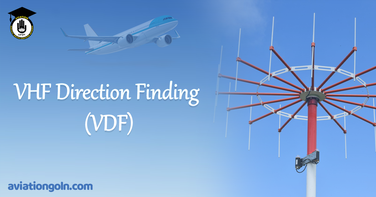
VHF Direction Finding (VDF) is a foundational, robust radio navigation technique used to determine the bearing (direction) of a Very High Frequency (VHF) radio transmission originating from an aircraft. While modern satellite-based navigation and advanced surveillance techniques dominate the current Air Traffic Management (ATM) landscape, VDF remains a critical, ubiquitous tool. It provides a vital layer of redundancy, assists in resolves positional uncertainty, and enhances Air Traffic Control (ATC) situational awareness, particularly in busy terminal environments or area with limited radar coverage.
The core operational principle is elegant in its simplicity: by analyzing how a specific radio signal arrives at a specialized ground-based antenna array, the VDF system can instantaneously calculate the relative or magnetic bearing of the transmitting source. This crucial directional data assists pilots in navigation and controllers in identification, thereby maintaining the procedural safety and efficiency of air traffic flow.
VHF Direction Finding (VDF)
Definition and Regulatory Context
Radio Direction-Finding within ICAO Standards
According to ICAO Annex 10, Volume II (which incorporates definitions originally established by the International Telecommunication Union – ITU), Radio Direction-Finding is formally defined as:
“A radiodetermination method that uses the reception of radio waves to determine the direction of a transmitting station or object.”
This definition places VDF under the broader umbrella of radio navigation aids. While direction-finding technology applies to various frequency bands and operational contexts, VHF Direction Finding is uniquely significant in civil aviation because the VHF band (118 to 137 MHz) is the primary medium for air-ground voice communications. VDF leverages these standard, existing communications to provide navigation and surveillance intelligence without requiring additional equipment aboard the aircraft.
VDF System Description and Key Components
A VDF installation is a ground-based navigational aid (NAVAID) integrated into an Air Traffic Services (ATS) unit. It comprises several synchronized technological elements:
Advanced Antenna Array
The antenna system is the sensor of the VDF. It utilizes a multi-element array (typically arranged in a circle) configured in specific technical designs, such as Adcock or Watson-Watt systems.
- Operational Mechanism: This circular configuration allows the system to compare the incoming signal’s characteristics—specifically phase and amplitude—as they arrive at different physical elements within the array.
- Site Considerations: The antenna must be situated in a location free of obstructions and multi-path reflectors (such as large buildings, hangars, or fences) to prevent signal distortion that would result in bearing errors.
Precision VHF Receiver
The receiver is tuned precisely to the operational frequency of the relevant ATS unit (e.g., Tower, Approach, or Center frequency).
Operational Mechanism: The receiver processes the signals transmitted by any aircraft communicating on that designated frequency within the ground station’s line-of-sight range. It must possess high sensitivity to lock onto weak or brief transmissions.
Signal Processing Unit
This unit acts as the mathematical engine of the VDF system.
Operational Mechanism: It utilizes complex algorithms to analyze the variations in phase difference or signal strength detected by the antenna array. By comparing these subtle differences, it computes the azimuth (bearing) of the transmission source relative to the VDF station.

Important Note: Antenna Site Selection
The accuracy of a VDF system is heavily dependent on its physical environment. VDF systems use line-of-sight propagation. Any local obstructions or multi-path interference (signals bouncing off nearby structures and arriving at slightly different times) will distort the phase measurements, leading to erroneous bearing calculations.
Operational Principles: The Mathematics of Arrival
Modern VDF systems primarily utilize the Phase Difference Method or the Doppler Effect Method to calculate bearings.
The Phase Difference Method
This technique calculates the direction by measuring the subtle time (phase) difference of the same signal arriving at different elements of the antenna array.
- A minimum of three (often five to eight) antenna elements are arranged equidistant from a center pole.
- An incoming signal reaches the element closest to the transmitter slightly before reaching the others. This arrival time difference corresponds directly to a difference in the signal’s electrical phase at each element.
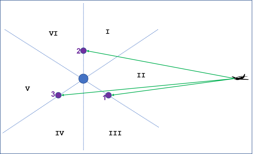
- The signal processor compares these phase relationships simultaneously. By solving trigonometric equations based on the known physical separation of the antennas, it determines the precise direction from which the wavefront arrived. Conceptual logic would show that if Element A receives the signal before Element B, and Element B before Element C, the source must reside within the specific arc defined by the geometric overlap of those conditions.
The Doppler RDF Method
Doppler Radio Direction Finding (RDF) electronically simulates the motion of a single antenna element moving rapidly in a circle. As the “moving” antenna travels toward the transmitter, the received frequency is slightly higher; as it moves away, the frequency is slightly lower (the Doppler shift). The system analyzes this frequency shift to determine the azimuth of the incoming signal. Doppler systems are generally more robust in environments prone to multi-path interference compared to pure phase-comparison systems.
Operational Modes: Bearing vs. Fix
Single-Station Operation: Angular Information Only
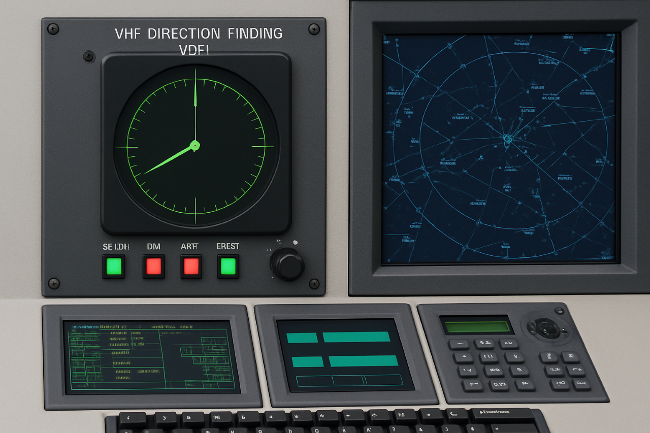
When operating as a standalone unit, a single VDF station can provide only the angular bearing of the transmitting source relative to the ground installation. While useful, it cannot provide range information.
Operational Use: Ideal for providing navigational assistance to pilots by giving them a specific magnetic direction to or from the airport (e.g., “Your bearing from the station is 220°”).
Multi-Station Triangulation: Positional Information
To determine the exact location of the aircraft (a “fix”), bearings must be taken from two or more geographically separate VDF stations simultaneously.
- Triangulation Technique: The computed bearings from each station are plotted on a situational display. The point where these lines of position intersect represents the aircraft’s fixed position.
- Operational Use: Multi-station triangulation provides a powerful, independent means of establishing aircraft location, making VDF a versatile backup surveillance tool, particularly in non-radar environments.
VDF Performance and ICAO Accuracy Classifications
The precision of VDF bearings and fixed positions is categorized by ICAO into standard accuracy classes.
ICAO Bearing Accuracy Classification
| Class | Accuracy |
| A | Within 2° |
| B | Within 5° |
| C | Within 10° |
| D | Worse than Class C |
Class B is the standard minimum acceptable accuracy typically required for operational VDF procedures (like homing or approaches). Class A systems provide high precision often used for primary navigation references.
ICAO Estimated Position Accuracy Classification (for Multi-Station Arrays)
When multiple bearings are used to triangulate a position, the accuracy depends on the angular geometry and the class of the individual bearings.
| Class | Estimated Position Accuracy |
| A | Within 5 NM |
| B | Within 20 NM |
| C | Within 50 NM |
| D | Worse than Class C |

Practical Applications of VDF in Modern Aviation
VDF technology serves five primary operational and safety functions in contemporary Air Traffic Management and flight operations.
1. Controller Situational Awareness & Surveillance Correlation
For decades, VDF has provided controllers with an independent confirmation of an aircraft’s relative position.
- Integrated surveillance method: When connected to modern surveillance displays, VDF acts as a correlation aid. The system overlays a directional strobe or highlight that identifies exactly which radar target made the voice transmission.
- Operational benefit: In complex terminal airspace, particularly where multiple aircraft use similar callsigns (e.g., flight numbers from the same airline), this instantaneous identification narrows the controller’s focus to a specific segment of the sky, significantly reducing search time and the risk of misidentification.
2. Navigational Assistance and Terminology
Pilots encountering equipment failure or disorientation can request bearing information from ground stations. These bearings are provided using standardized aviation terminology:
- QDM – The Magnetic Bearing To: The pilot must fly this magnetic heading (in zero wind) to reach the VDF station. This is the most common bearing given for homing.
- QDR – The Magnetic Bearing From: This is the aircraft’s magnetic bearing measured from the VDF station (the reciprocal of the QDM). It represents the radial the aircraft is currently on.
- QTE / QUJ: These represent True bearings from the station (QTE) and to the station (QUJ), though they are less commonly used for procedural navigation than the magnetic QDMs/QDRs.
3. Homing
“Homing” is the procedural request by a pilot for a series of sequential QDMs at regular intervals to navigate directly toward a VDF station (usually the airport).
Request Intervals: Initially, QDMs might be requested one minute apart. As the aircraft nears the station, the frequency of requests increases (e.g., every 30 or 15 seconds) to account for the increasing angular sensitivity near the aid.
4. VDF Instrument Non-Precision Approaches
VDF data can be used as the primary navigational guidance for a structured non-precision approach to an aerodrome. These procedural approaches are published in the national Aeronautical Information Publications (AIPs).
Procedural Overview: Pilots use specific QDMs and associated descent altitudes to navigate and execute the approach. Example installations include Cranfield Airport (EGTC) in the UK.
5. Frequency Management and Enforcement
VDF equipment is used by law enforcement and regulatory agencies to locate the physical source of illegal, unauthorized, or continuous (“stuck microphone”) transmissions on safety-critical Air Traffic Control frequencies.
Terminology Summary: Q-Codes for Bearing
- QDM: Magnetic bearing TO the station.
- QDR: Magnetic bearing FROM the station.
- QTE: True bearing FROM the station.
- QUJ: True bearing TO the station.
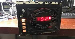
VDF Frequency Band and Technical Constraints
Line-of-Sight Limitations
VDF operates strictly in the Very High Frequency (VHF) band (118 to 137 MHz), which is the international standard band for civil aviation communication. This means VDF signals follow line-of-sight propagation paths.
- Practical Constraint: VDF coverage is fundamentally limited by the curvature of the Earth and intervening terrain. To obtain a reliable bearing, there must be an unobstructed path between the aircraft antenna and the ground VDF antenna.
- Distant Operations: If an aircraft is too low or too far away (behind terrain or the horizon), the VDF system cannot provide accurate bearing or position data.
Limitations of Multi-Path and Polarization Errors
- Multi-Path Error: The major technical limitation. Signals reflected off buildings, hills, or other large objects arrive at the antenna slightly later than the direct signal. This “ghosting” distorts the phase difference, causing bearing inaccuracies (errors can exceed 10° in extreme cases).
- Polarization Error: Occurs when the incoming wave is not purely vertically polarized (e.g., when an aircraft is banking sharply). This can cause signal nulls or errors, though Adcock antenna arrays are designed to mitigate this effect.
Homing Technique vs. Tracking
Homing (flying a QDM heading in no wind) does not correct for drift. If a crosswind exists, the pilot will fly a curved path toward the station. Tracking (calculating drift and flying a ground track) requires additional navigational tools. VDF only provides the direction; it does not solve the wind triangle.
Standard Radiotelephony Procedures
Phraseology and Confirmation
ICAO does not define a single, universally standardized phraseology for VDF, leaving specific examples to national civil aviation authorities (e.g., UK CAA CAP 413). However, ICAO Annex 10, Volume II establishes general requirements:
- Pilot Transmission Length: For the ground station to calculate an accurate bearing or position, the pilot must make a transmission of appropriate length (often requested as a simple count-down or a longer call).
- Accuracy Class Specification: When providing a bearing or position, the controller must specify the associated accuracy class.
- Readback Requirement: The pilot must read back the received bearing information, including the accuracy class, to confirm correct reception (e.g., “QDM 090 DEGREES, CLASS B, DVK1208″).
- Fix Presentation: Multi-station position fixes are provided using coordinates (degrees and minutes), followed by the cardinal directions NORTH/SOUTH and EAST/WEST.
Procedural Dialogue Example
- Pilot: TOWER, DVK1208, REQUEST QDM.
- Controller: DDV1208, DDV1208, TRANSMIT FOR BEARING.
- Pilot: TOWER, DVK1208, TWO, ONE…DVK1208.
- Controller: DVK1208, QDM 110 DEGREES, CLASS B.
- Pilot: QDM 110 DEGREES, CLASS B, DVK1208.
Key Takeaways / Core Points at a Glance
| Concept | Description |
| Operational Function | Ground-based aid that calculates the directional bearing of an aircraft based on its VHF voice transmissions. |
| Core Technology | Compares the signal’s phase (Phase Difference Method) or frequency shift (Doppler Method) arriving at different array elements. |
| Key Components | Circular antenna array, precision VHF receiver, signal processing computer. |
| Primary Band | Civil Aviation VHF band (118 – 137 MHz). Signals follow line-of-sight propagation. |
| Accuracy Classes | Classified by ICAO: Class A (±2°), Class B (±5°), Class C (±10°). Class B is typically the operational minimum. |
| Modes | Standalone station provides bearing only. networked stations provide a fixed position (Fix) via triangulation. |
| Applications | Correlating radar targets in ATC, providing QDM/QDR navigational assistance, homing, non-precision approaches (PDF Approach), and pinpointing unauthorized transmissions. |
| Major Limitation | Susceptible to multi-path interference from terrain/obstructions, causing bearing errors. Requires line-of-sight propagation. |
Frequently Asked Questions (FAQ)
1. What is the primary operational purpose of VHF Direction Finding (VDF)?
VDF is primarily used as a non-precision navigational aid for pilots (homing and approach), a surveillance tool for controllers (target identification and correlation), and a redundant navigational backup, particularly in environments with limited radar coverage.
2. What is the difference between QDM and QDR in VDF navigation?
QDM is the magnetic bearing to the VDF station. This is the heading a pilot should fly (in zero wind) to go directly to the aid. QDR is the magnetic bearing from the station.
3. Why is VDF susceptible to errors from buildings and terrain?
VDF systems calculate bearings based on signal characteristics like phase or frequency. Large objects can reflect the signal. When the primary signal and the reflected “echo” arrive at the antenna at slightly different times (multi-path), they interfere, distorting the signal’s characteristics and causing the processing unit to compute an incorrect bearing.
4. How does multi-station triangulation differ from single-station VDF?
A single station provides only the angular bearing (direction) to or from the aid, not a precise fix. networked VDF stations allow multiple bearings to be plotted simultaneously; the point where these bearings intersect (triangulate) provides the exact coordinates (the “fix”) of the transmitting source.
5. Is standard phraseology required for VDF operations?
While ICAO Annex 10 Vol. II provides general procedural guidance, it does not mandate standard phraseology. Pilots and controllers must refer to national phraseology manuals (such as CAP 413 in the UK) which provide the approved communication standards for VDF procedures.
6. Why are VDF approaches considered “Non-Precision”?
VDF approaches are classified as non-precision because they provide lateral (azimuth) guidance only. They do not provide the pilot with vertical (glidepath) guidance, unlike precision approaches such as ILS or GLS.
7. Is VDF technology compatible with digital radios and modern avionics?
Yes. VDF calculates the bearing based on the physics of the received radio wave itself (phase/frequency), regardless of whether the content of the transmission is analog voice or digital data.
8. Are VDF bearings True or Magnetic?
VDF bearings are calculated relative to the station’s orientation but are typically provided to pilots as Magnetic bearings (QDM/QDR) as these align directly with the pilot’s magnetic compass, which is the primary heading reference during procedural navigation. True bearings (QTE/QUJ) can be provided upon request.